Turbo boost and airflow calculator: turn a horsepower target into airflow, boost and pressure ratio for picking a turbo, or work from a known boost level to airflow and estimated power.
Turbo boost and airflow calculator
What do you want to find?
Engine and conditions
Turbos and the compressor map
Result
How the numbers are calculated
This follows the method Garrett lays out in its Turbo Tech 103 guide for plotting an engine on a compressor map. You need two numbers: the mass of air the engine flows, and the pressure ratio the compressor has to make.
Airflow (lb/min) = HP × air/fuel ratio × BSFC ÷ 60
Manifold pressure (psia) = airflow × 639.6 × (460 + manifold temp °F) ÷ (VE × RPM ÷ 2 × displacement in cubic inches)
Pressure ratio = (manifold pressure + intercooler/piping loss) ÷ (ambient pressure - inlet restriction)
Corrected flow = airflow × √((inlet temp °F + 460) ÷ (reference temp °F + 460)) ÷ (compressor inlet pressure ÷ reference pressure)
In the default mode, airflow comes from Garrett's rule of thumb that turbocharged gasoline engines make about 9.5 to 10.5 horsepower (at the flywheel) per lb/min of air - its catalog quotes 10 to 11. Switch to air/fuel ratio and BSFC to use the full formula; Garrett's worked example uses an air/fuel ratio of 12 and a BSFC of 0.55, which works out to about 9.1 HP per lb/min.
In boost mode the same manifold pressure equation runs in reverse: ambient pressure plus gauge boost gives manifold pressure, which gives airflow, which gives an estimated horsepower at your HP-per-lb/min figure.
Choosing the inputs
Air/fuel ratio and BSFC go together. Both numbers have to describe the same fuel: alcohol fuels run much richer air/fuel ratios and burn more fuel per horsepower, so a gasoline air/fuel ratio paired with an E85 BSFC gives the wrong airflow. The fuel menu fills matching pairs from Garrett's Knowledge Center - pump gas 11.5 and 0.46, E85 8.5 and 0.60, methanol 5.0 and 1.05, race gas 12.5 and 0.42 - or the 12 and 0.55 from its Turbo Tech 103 example. Note that Garrett's own text on that page puts turbocharged gasoline engines at a BSFC of "0.50 to 0.60 and higher" and says race fuels and aggressive tuning are needed to reach the low end, so its 0.46 pump-gas table value is optimistic.
Why the default differs from our fuel calculators. The default 10 HP per lb/min is the same as a BSFC of 0.50 at an air/fuel ratio of 12 (60 ÷ (12 × 0.50) = 10). Our fuel pump and AN line calculators use BSFC 0.60 for turbocharged gasoline, because a higher BSFC sizes pumps and lines on the safe side. Entered here with an air/fuel ratio of 12, BSFC 0.60 gives 8.3 HP per lb/min - 20% more airflow for the same horsepower, which is a more conservative turbo choice rather than a different engine. The same goes for alcohol: those calculators use a turbocharged BSFC of 0.85 for E85 and 1.30 for methanol, richer than Garrett's 0.60 and 1.05 here.
Volumetric efficiency. Garrett's table starts at 80% for 2-valve heads, 85% for 3-valve, 90% for 4-valve and 95% for 5-valve. The same Garrett page gives peak ranges of 95-99% for modern 4-valve heads and 80-95% for 2-valve designs (Turbo Tech 103 says 88-95% for 2-valve), so the presets sit at the low end - treat them as a conservative start. VE peaks at the torque peak on a well-tuned engine, so if you have a dyno sheet you can do better than a preset.
Manifold temperature. Garrett puts intercooled setups at typically 100-130 °F and non-intercooled at 175-300 °F. Hotter air is less dense, so the same airflow needs more manifold pressure.
Losses. Air filter and inlet ducting pull the compressor inlet below ambient (Garrett's example uses 1 psi), and the intercooler and piping cost pressure between the compressor and the manifold (Garrett's examples use 2 psi; 1 psi or less on a well-designed system, 4 psi or more on restrictive OEM setups). Both raise the pressure ratio the turbo has to make for the same boost - which is why the calculator can show a pressure ratio above 1 even when the manifold needs no boost.
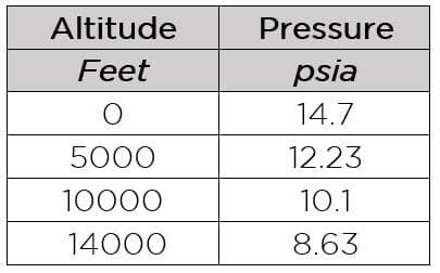
Altitude. Ambient pressure comes from the standard atmosphere - 14.70 psia at sea level, about 12.23 psia at 5,000 ft. Less ambient pressure means a higher pressure ratio for the same gauge boost, which is why the same turbo works harder in Denver.
Corrected flow and twin turbos
Corrected flow. Garrett's compressor maps are drawn against corrected air flow - that is what the flow axis on its maps says - not the actual lb/min the engine swallows. Corrected flow scales actual flow to the map's reference inlet conditions; NASA defines this "corrected weight flow" as flow × √θ ÷ δ, where θ and δ are the inlet temperature and pressure divided by the reference values. At altitude, or with hot inlet air, corrected flow is higher than actual, so your point sits further right on the map. The current Garrett maps we checked don't print their reference temperature and pressure, so the calculator doesn't assume them - though some older Garrett maps print them in the flow-axis label (one reproduced at stealth316.com reads 545 °R and 28.4 in. Hg, about 85 °F and 13.95 psia): enter the reference conditions your turbo maker gives for its maps, plus the air temperature at the compressor inlet, and it adds a corrected flow. Without them the map point is actual flow.
Twin turbos. Garrett's Boost Adviser matches a twin setup by halving it - "the horsepower and engine displacement inputs will be divided by two and each turbo will be matched to support half of the total." Each compressor flows half the airflow at the same pressure ratio, so set Turbos to 2 to get the point for each one.
Reading the map. Turbo Tech 103 calls the surge line "the left hand boundary of the compressor map", with "a region of flow instability" to its left, and the choke line the right-hand boundary, which on Garrett maps is "typically defined by the point where the efficiency drops below 58%" - past it, "a larger compressor is necessary." Your point should sit inside the map, right of the surge line and left of choke. Garrett also plots a second point at the rpm where it expects peak torque, because a compressor that looks good at peak power can end up near or over the surge line at lower engine speeds. To get that point here, switch to boost mode and enter your boost, the torque-peak rpm and the VE there.
Volume flow (CFM) is shown at Garrett's sea-level air density of 0.076 lb/ft³. Compressor maps are plotted in corrected mass flow (lb/min) against pressure ratio - use those two numbers to place your point. These are estimates for narrowing turbo choices; a turbo's actual fit depends on its map, turbine side and your tune.
Boost is only half the system - the fuel side has to keep up. Check pumps and injectors with our fuel pump and injector calculator, and line sizes with the AN fuel line size calculator.
BMW M30 Billet Intake Manifold + Integrated Bell Air/Water Intercooler Building a boosted M30? See our billet intake with the air/water intercooler built in.Sources: Garrett Turbo Tech 103 (Expert) · Garrett - understanding calculations to turbo any engine (VE, AFR and BSFC tables, corrected air flow map) · Garrett Boost Adviser (twin turbos) · Garrett catalog vol. 8 (HP per lb/min) · Garrett turbo system optimization (CFM conversion) · Garrett elevation pressure chart · National Weather Service pressure altitude formula · NASA Glenn - corrected airflow · stealth316 - legacy Garrett compressor map reference conditions · More tools: all podio1 calculators